You can download this tutorials in pdf from here.
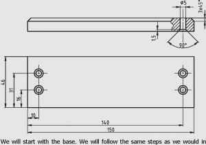
In this tutorial you will create a picture holder, consisting of a rectangular base with 4 vertical axes on it. You will get to know some new features, such as the ‘Chamfer’ command. You will also get to know the ‘Assemblies’ command. We will also use extrude and extruded cut commands in this tutorial.
The details of assembly to be made are
We will start with base, followed by the pegs and finishing with the assembly.
BASE
In this part we make the base of picture holder
1. Use a piece of material with following dimensions: 150x46x12.
2. Chamfer the ribs of the top plane.
3. Drill four holes with a diameter of Ø5.
4. Counter bore the holes on the bottom plane.
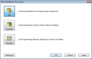
1) Start SolidWorks and open a new file by clicking on New. Click on the ‘Part’ button in the menu first and then click on ‘OK’.
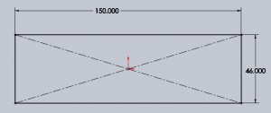
2) Click on ‘Top Plane’ in the left column of the Featu-reManager. In this plane we will make a sketch. Click on ‘Sketch’ in the CommandManager (which is the menu at the top of the screen) to show the right buttons. Then click on Rectangle to draw a rectangle and draw a rectangle with one corner at the origin. Now dimension the rectangle using smart dimension  as 150X46 as shown in figure
Now exit the sketch by clicking on exit sketch button ![]() .
.
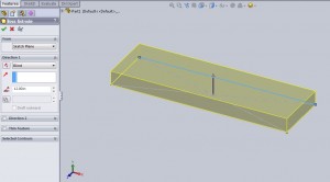
3) Go to features tab and click on the extrude boss/base button and extrude the current sketch to 12 inch and exit the extrude tool.
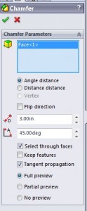
4) Now select the top plane of the extrude and click on chamfer button
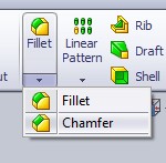
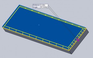
Set the chamfer width to be 3 inch and angle to be 45 degrees as shown.
you can see the full preview as
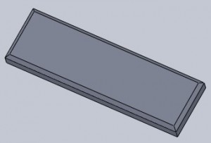
Now click on green check mark to exit the chamfer tool and you will see the resultant structure as
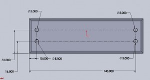
5) Now select the top plane of the base and click normal to & sketch and draw four circles as shown in figure below.
To accomplish this first draw to construction lines each at a distance of 16 and 31 in from the bottom edge and two construction lines at a distance of 10 and 140 from the left edge. Now with the corners of the rectangle thus formed as the centers draw four circles of dia 5.
Exit the sketch ![]() by clicking on exit sketch button and click on extruded-cut button in features tab.
by clicking on exit sketch button and click on extruded-cut button in features tab.
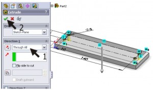
You will see the material removed from the model as shown, set the depth as through all, (which means the material will be removed for the entire length of the object in that direction) and click OK to exit the tool.
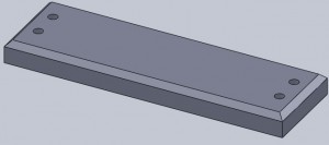
The resultant structure will be like
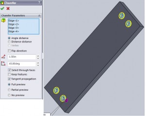
6) Rotate the structure to the bottom surface. Click the chamfer button as shown previously in features tab, select the edges of the four holes for chamfering. Enter the chamfer width as 1.5in and angle as 45 degrees and click ok to see the base as
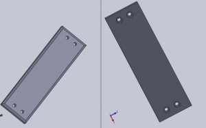
We have the final shape of the base as
PEGS
To make the pegs we plan first on how to do it.
We will create this model in three steps:
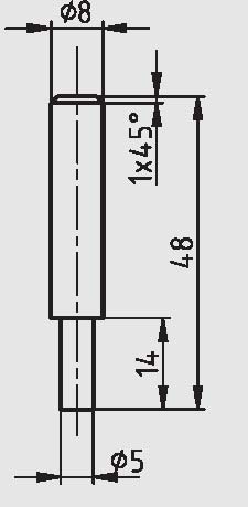
- We will take the basic material of Ø8 x 48.
- We will cut a part at the bottom of the axis to Ø5 x 14.
- We will make a sloped edge at the top.
Procedure
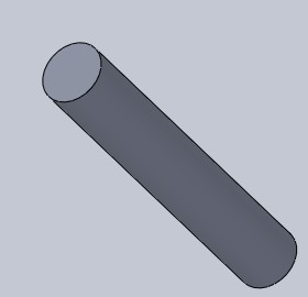
1) Click on new then select part and click ok. Now select top plane and click normal to ![]() and sketch button
and sketch button ![]() to start sketching. Make a circle using center circle button
to start sketching. Make a circle using center circle button ![]() and set its diameter to 8inch using smart dimension tool
and set its diameter to 8inch using smart dimension tool  . Now extrude the circle after exiting the sketch by clicking on exit sketch button
 ![]() . and set the extrude length to 48 inch. The resultant structure of the step is
. and set the extrude length to 48 inch. The resultant structure of the step is
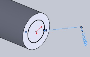
2) Now click on one end of the peg and draw a circle of 5 inch in diameter as shown in figure below.
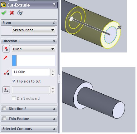
Go to features tab and select the extruded cut button 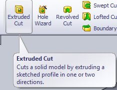 and set the depth as 14, type as blind, check the flip side cut option and click ok.
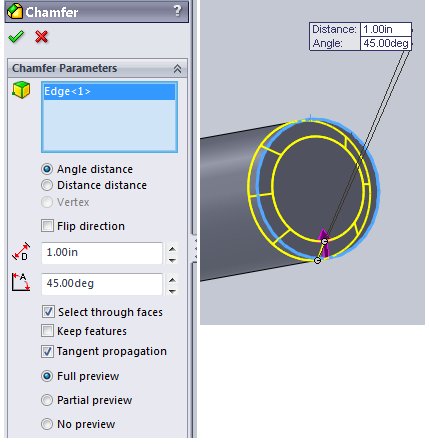
3) In the third step we chamfer the other side of the pin with a chamfer of 1x45degrees. To do this go to features tab click on fillet -> chamfer

Then click on the other side of pin and set the chamfer distance as 1inch and angle at 45 degrees and click ok.
Now save the part as picture_holder_pin.sldprt
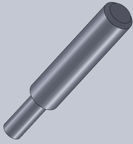
The final part will look like this..
The Assembly
We are at the final part of our tutorial. The two parts for the picture holder are ready. We
are going to assemble them in an assembly to create the complete product.
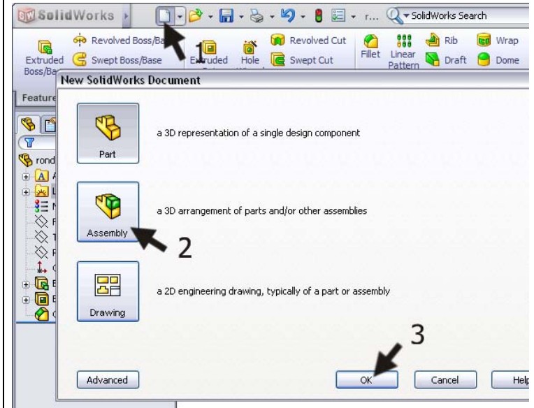
To do this click on new then assembly and click ok.
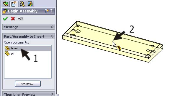
In the left hand pane browse for base and position it somewhere in the space.
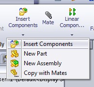
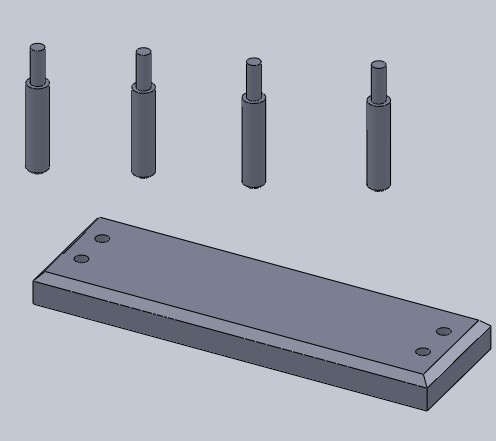
After that insert pins by clicking on insert components -> insert components and browser for pin and click on a random point in the space. Do it three times so that you will end up with four pins as shown
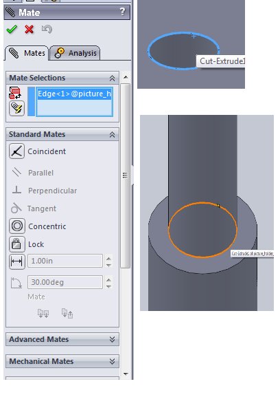
Click on mate button in features tab the n click on one edge of the circular hole on the base and other edge of the pin as shown in figure to form a mate. If the larger size of the pin is disappearing into the base then click on anti-aligned button to make them align into proper orientation and click ok (the green tick).
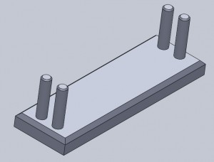
Now repeat the same for other three pins and you will see the final product as
—- Now you have assembled the picture holder —-
Files in this tutorial

