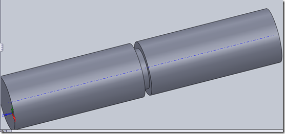
Revolved Cut is another basic features used in SolidWorks for part modeling / creation. In this tutorial we show how to use revolve cut to model parts.
Level: Beginners
First we are going to create a cylinder and then we are going to make a square cut in the middle by using revolve cut feature.
Video Tutorial
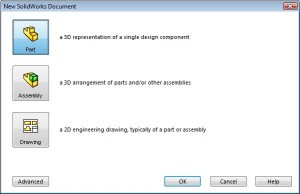
Open Solidworks and click on new and then click on part and click ok as shown.

Then click on top plane and sketch a circle of 2 inch in diameter as shown and exit the sketch by clicking on exit sketch button ![]() .
.
Then go to features tab then click on extrude boss/base button 
and extrude the current sketch to a length of 10 inch.
and click ok.
Now select the right plane click normal to 
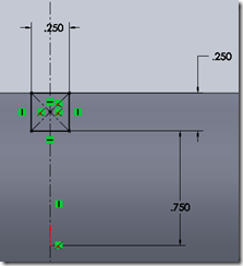
and then  then click on sketch and draw a square of .25inch length and .75 inch away from the center of the cylinder as shown in figure below. Use centered rectangle tool
  to do this. Notice that the square is in the middle of the cylinder with its symmetric to y-axis.
Now click on exit sketch button ![]() and exit the sketch.
and exit the sketch.
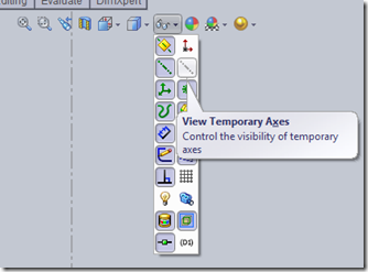
In the menu in the workspace click on view temporary axes to display the axis of the cylinder.
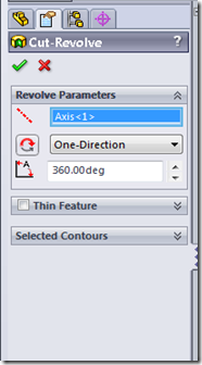
Now go to features tab then click on Revolve cut feature 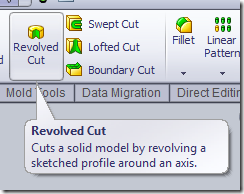
Select the newly created sketch as the planar feature to revolve then click on axis button (highlighted in blue) and click on the axis of the cylinder.
and click OK.
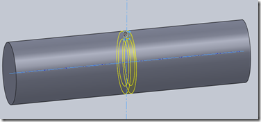
You will see the final part as
Download the file used in this tutorial.


