This tutorial is about extruded surface feature in SolidWorks. This tool is similar to extrude feature in part modeling. The main difference between both is that we are going to draw a surface instead of a part / body. Also the profile can be open / closed. If you extrude a circle with extrude feature in part modeling you will get a cylinder, but here you will get a cylindrical surface. You can just draw a line and extrude to produce a rectangular surface.
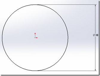
Open SolidWorks and create a new part document an sketch a circle of 10mm in diameter on the front plane.
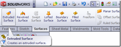
Exit the sketch and go to surfaces tool bar and click on extruded surface button
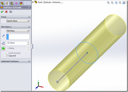
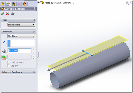
select the circular sketch as the sketch to extrude and enter the 50 mm as length to extrude, You can select blind extrude in one direction / midplane extrude, where by it extrudes evenly on both sides of the front plane.
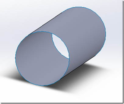
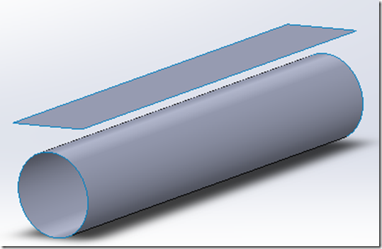
The other options, draft  lets you change the angle of extrude, so that instead of a cylinder you will end up with a cone, the cap end option lets you close the open ends of the cylinder. Click ok & you will see the circular surface as
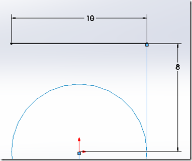
You can also use a open profile to extrude instead of a closed one. To do this create a simple line of 10mm in length and repeat the above steps to see it in action.
